

SIMATIC S5-95U and S5-115U: Migration Paths to TIA Portal
SIMATIC S5-95U or S5-115U still running? How to back up the program, converter versus rebuild, the TIA V21 hurdle and adapters that keep the wiring.
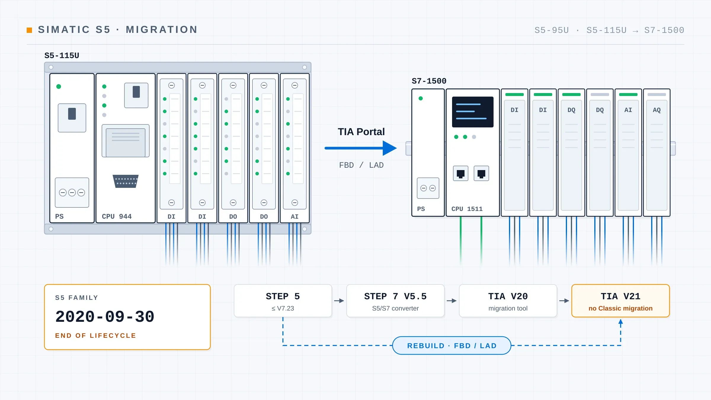
A SIMATIC S5-95U or S5-115U that still runs a plant today does so without any backing from the manufacturer. According to Siemens UK, the product lifecycle of the entire S5 family ended on 30 September 2020; since then Siemens has supplied no spare parts and carried out no repairs. The plant itself runs exactly as it did the day before. What has changed is the failure scenario: a solution then has to come from outside Siemens, and every program change depends on STEP 5 and on a PC that can still run it.
This article is for maintenance and operations managers with an S5-95U or S5-115U in the field. It works through what the status of both series means, what to back up while the controller is still running, which two routes lead into TIA Portal, and where the known pitfalls are. Every factual statement links to its source; where the sources are thin, the text says so.
What the status of the S5-95U and S5-115U means today
The Siemens migration guide from S5 to S7-1500 (entry 105106251, in German) describes the phase-out as follows: S5 components have been phased out since 2003 and are no longer manufactured, and from then on spare parts were only available on an exchange basis. A chart in the guide separates the groups S5-115, S5-135/155 and S5-90/95/100 and shows a ten-year spare-parts phase for each. It gives no actual dates per series.
So exactly when the 95U and the 115U each dropped out of spare-parts supply cannot be pinned down with a source. I have not found a Siemens document that gives dates per series. For a decision at your own site this is secondary: as of 30 September 2020, the whole family is closed.
Which devices this covers
The S5-115U is a modular system built on a mounting rack. The Siemens manual (entry 1085937) lists the CPUs 941, 942, 943 and 944; the CPU 945 has its own device manual (1086944), which the migration guide also references.
The S5-95U is a compact unit. According to its system manual (German), the unit itself carries 16 digital inputs, 16 digital outputs, 8 analog inputs and 1 analog output, plus counter and interrupt inputs. It is expanded with S5-100U modules. This difference from the 115U matters a great deal when the cabinet is rebuilt, as shown further down.
First step: back up the S5 program while the plant is running
The first thing to secure on an S5 plant is the program in the CPU. If the CPU fails without a backup, the function survives only in the behaviour of the machine and in the operators' memory. That is why the backup comes before any discussion about hardware.
Is a PG cable enough to pull data from the S5 with TIA Portal?
That is a question asked on the SPS-Forum, specifically about the 6ES5 734-1BD20 cable. The cable alone will not do it. According to the IBHsoftec wiki, the S5 programming port is a 20 mA current loop (TTY) using the AS511 protocol. The PC side therefore needs hardware and software that handle exactly that.
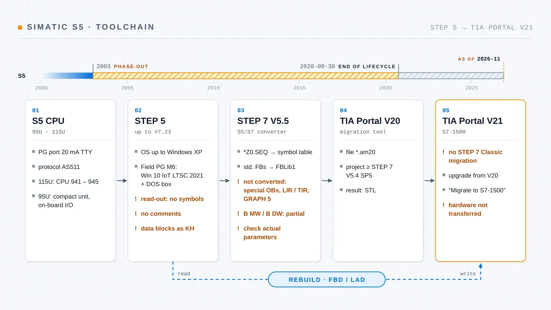
In its migration guide, Siemens explicitly advises against standard notebooks and recommends a Field PG with an S5 interface and an EPROM programmer. For taking over the program, the same guide routes you through STEP 7 V5.5 first, with TIA Portal only after that. Beyond Siemens, users on the SPS-Forum mention USB or LAN adapters that work with programs such as PG2000 or "S5 für Windows".
Getting STEP 5 and keeping it running
Siemens FAQ 6002243 lists STEP 5 versions up to V7.23 and operating systems up to Windows XP. In a 2016 post on the Siemens forum, STEP 5 was described as discontinued, with no download and supply only through a support request. Whether STEP 5 can still be ordered from Siemens today, I was unable to establish. Wikipedia gives 1 October 2005 as the discontinuation date; I have not found a Siemens source for that date.
Even an existing Field PG is no safe bet. A post on the SPS-Forum quotes Siemens FAQ 109997556: STEP 5 V7.23 HF2 no longer starts on the Field PG M6 after current Windows 11 updates, and the released configuration is Windows 10 IoT Enterprise LTSC 2021 with a DOS box. I could not retrieve the FAQ text itself. If you have a PG on which STEP 5 runs, treat it like a piece of test equipment and do not update it in passing.
Can the program be read out without the project?
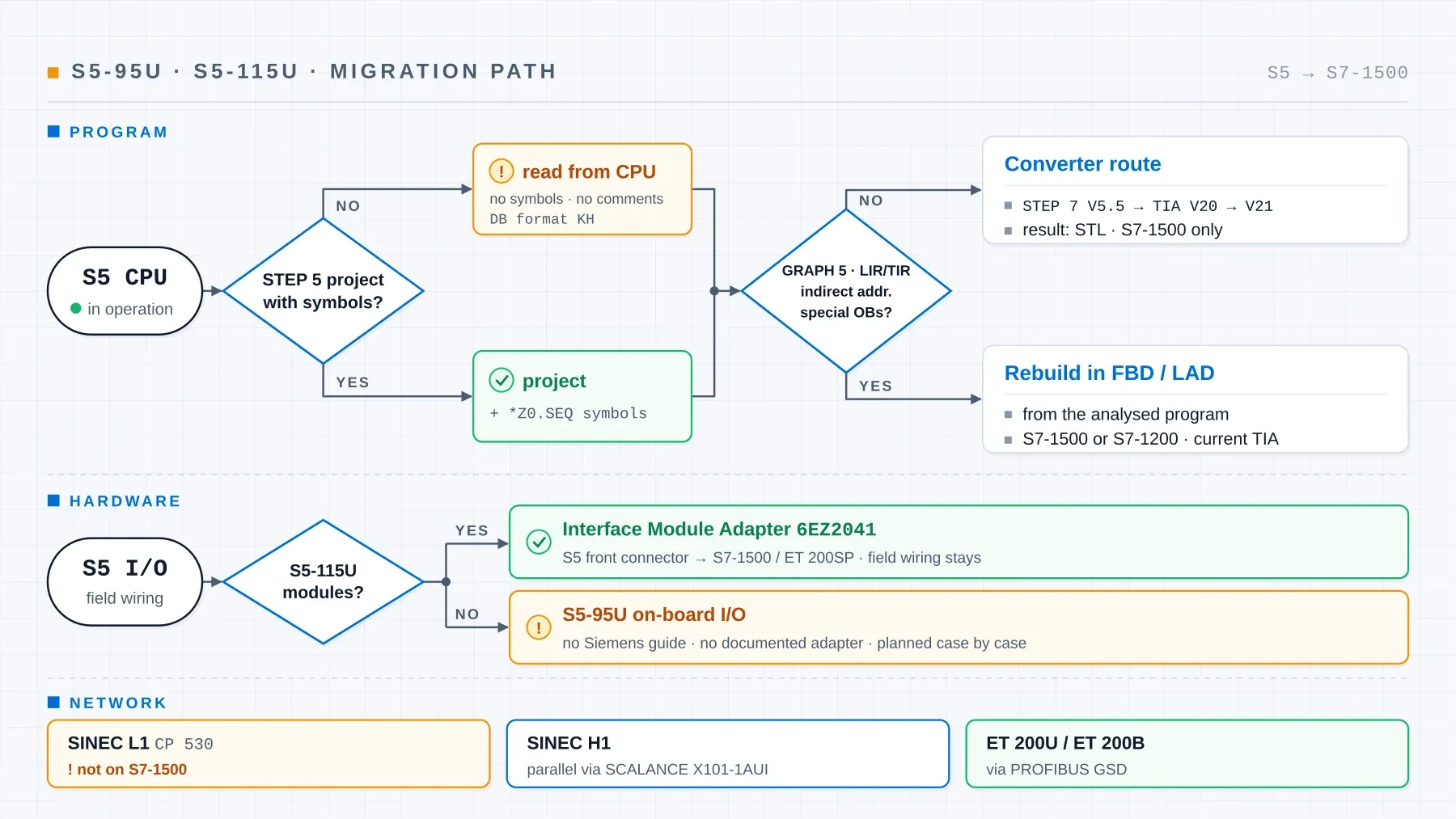
Yes, the program can be read from the CPU. The same SPS-Forum thread describes what is missing afterwards: symbols and comments are not stored in the controller, so they are lost. Data blocks only come across in KH format, that is, as hexadecimal values.
Before anyone reads from the CPU, it pays to look for the project: on the old programming device, at the machine builder, in the electrical design archive. The assignment list (file *Z0.SEQ) is particularly valuable because it holds the symbols. According to the guide, Siemens carries it over into the STEP 7 symbol table during conversion.
Two routes into TIA Portal: converter or rebuild
On the program side there are two fundamentally different routes. The first translates the S5 code mechanically. The second reads it, works out what it does, and rebuilds it in TIA Portal.
The converter route and its documented limits
STEP 7 V5.x comes with an S5/S7 converter. What it can and cannot do is set out in the Siemens converter manual "Von S5 nach S7" (entry 1118413, in German):
- Not converted: OBs for special functions, absolute addressing with LIR and TIR, and sequencers written in GRAPH 5.
- Integrated blocks and standard function blocks are replaced by FCs from the FBLib1 library.
- Indirect addressing via
B MWorB DWis only partly converted, and the result is heavily bloated. - Actual parameters have to be checked by hand. Anything that cannot be converted ends up as a comment in the output.
A thread on the SPS-Forum shows what that looks like in practice: after conversion, one user reports 400 errors caused by indirect addressing.
According to the guide, Siemens recommends two steps, first from S5 to STEP 7 V5.5 and from there into TIA Portal. Whether the converter is still included in STEP 7 V5.6 or V5.7, I could not confirm; the guide refers to V5.5. What comes out is an STL program with the structure of the S5 original. That rules out the S7-1200, which according to the SPS-Forum cannot run STL.
Rebuilding from the analysed program
In a rebuild, the S5 program is read network by network. Without symbols, every network has to be interpreted, as the SPS-Forum puts it: which input is the limit switch, which flag is the enable, which counter holds the piece count? The analysis produces a functional specification, and that becomes the yardstick for the new program, for testing and for acceptance.
For migrations, I rebuild in TIA Portal using FBD and LAD. The reason is maintenance: in online status, the team can see signal by signal which condition is missing and can read the program on its own when something stops. SCL is kept for calculations. Why that split makes sense is explained in the article on PLC programming languages under IEC 61131-3. The new program is tested in simulation before the conversion, so logic errors turn up at the desk before the plant is shut down.
Of the old toolchain, a rebuild only needs something that can read the S5 program; the new program is written directly in the current TIA version. How such a retrofit runs as a project is described on the control system retrofit page.
The bottleneck: TIA Portal V20 and V21 when migrating from STEP 7 Classic
Anyone taking the converter route ends up with an intermediate result in STEP 7 V5.5, that is, STEP 7 Classic. Getting from there into TIA Portal has become narrower with every TIA version:
- According to the Siemens migration guide S7-300 to S7-1500 (in German), the Classic project must be at least at STEP 7 V5.4 SP5.
- From TIA Portal V20 onwards, migration works only through the migration tool, which produces a
*.am20file, according to the Siemens documentation (in German). - TIA Portal V21 no longer migrates STEP 7 Classic projects at all, as its overview of migration options states. The route goes via V20 and then an upgrade to V21.
- Only inside TIA Portal does "Migrate to S7-1500" follow, and according to the Siemens documentation the hardware is not transferred automatically.
For an S5 plant, this means that STEP 5, STEP 7 V5.5, TIA Portal V20 and a current TIA version all need working installations before the first line runs on the S7-1500. As described above, STEP 5 alone already raises the question of a suitable operating system.
Keeping the wiring: adapters for the S5 front connectors
On an S5-115U, the field wiring does not necessarily have to be redone when the controller is replaced. Siemens offers the Interface Module Adapter 6EZ2041-… for this purpose. According to the Siemens document (entry 83557459), it takes the existing S5 front connectors and connects them to an S7-1500 or an ET 200SP. The document includes a mapping table showing which 115U module corresponds to which S7-1500 module. The field wiring stays on the front connector, and the schematic does not change on the field side.
Phoenix Contact offers an adapter system for the S5-115U called VARIOFACE-S5-S7, but according to its data sheet (copy at a distributor) it targets the S7-300 and S7-400. If the S7-1500 is the target, plan with the Siemens adapter.
The special case of the S5-95U: left out of the Siemens guide
The Siemens guide explicitly covers only the S5-115U, S5-135U and S5-155U. Migrating the S5-95U and S5-100U is outside its scope. That is worth knowing before you go looking for a Siemens mapping table for the 95U.
On the 95U, the wiring of the on-board I/O terminates on the compact unit itself. I have not found a Siemens adapter designed for that on-board I/O, and the mapping table of the Interface Module Adapter refers to 115U modules. For the hardware side of a 95U there is therefore no predefined route; it is surveyed and planned case by case.
The program side is different. The questions are the same as for the 115U: backup via the programming port, missing symbols, the analog value format, communication. One user on the SPS-Forum asks whether an existing SINEC L2 cable can be reused as PROFIBUS when several S5-95U units are replaced by S7-1500 controllers. That can only be answered on site, by looking at cable type, length and condition.
Pitfalls after the switchover
The following points are either in the Siemens guide or come up as questions on the SPS-Forum. Each belongs in the analysis before a shutdown date is fixed.
Analog values: FB250, SLW 1 and SRW 4
The S5 analog format carries error, overflow and activity bits inside the value itself; the S7 format does not. The S7 nominal range is 27648. That is how chapter 9 of the Siemens manual "From S5 to S7" puts it.
Two forum questions show where this surfaces in daily work. One, in the thread "Analogwerte von S5 nach S7", is about the parameters of FB250. The converter replaces standard function blocks with FCs from FBLib1, but the actual parameters still have to be checked by hand. The other comes from moving an S5-115U to a CPU 1511: why does the carried-over code have SLW 1 and SRW 4 on the analog value? Shift instructions like these belong to the handling of the S5 format and its status bits, and they should not be left on an S7 value without checking.
Cycle time and choice of CPU
According to the guide, cycle times change after migration. Siemens advises checking beforehand whether the S5 CPU was running at its performance limit. That question can only be answered on the running plant, so before the S5 comes out.
System data blocks and special OBs
DB0, DB1 with the coupling flags, DX0 and the OBs from OB110 upwards do not exist on the S7-1500, according to the guide. Whatever depends on them in the S5 program has to be solved differently in the new one. On the converter route this shows up as a comment in the output; in a rebuild it shows up during the analysis.
Communication: SINEC L1, SINEC H1 and ET 200U
The guide distinguishes three cases. SINEC L1 via the CP 530 cannot be connected to the S7-1500. SINEC H1 can continue to run in parallel through a SCALANCE X101-1AUI. ET 200U and ET 200B distributed stations can stay in operation via PROFIBUS GSD. Which links a plant actually has therefore belongs in the survey, including the partner stations on neighbouring plants.
Operator panels
If an operator panel is connected to the S5 via AS511, it has to be considered together with the controller. According to a post on plctalk, the OP270 was the last Siemens HMI with AS511; an adapter from IBH is mentioned there as an alternative. This mainly matters if only the panel is to be replaced first. With the move to the S7-1500, the HMI is rebuilt anyway, usually in WinCC Unified.
A related question on the SPS-Forum asks whether a CPU 944 and an S7-1500 can be run in parallel for testing. I test the new program beforehand in simulation against the functional specification. What remains on site is testing the signals and sequences with the real mechanics.
Decision guide: converter or rebuild
| Criterion | Converter route | Rebuild in FBD/LAD |
|---|---|---|
| Source project with symbols | very helpful, otherwise STL without names | helpful, missing symbols are reconstructed |
| GRAPH 5, LIR/TIR, special OBs | not converted | solved anew from the function |
| Indirect addressing | partial only, heavily bloated | understood as a function and rebuilt |
| Tools | STEP 5, STEP 7 V5.5, TIA Portal V20, current version | STEP 5 or another reader, current TIA version |
| Target CPU | S7-1500 (S7-1200 cannot run STL) | S7-1500 or S7-1200 |
| Result | STL with S5 structure | FBD/LAD with meaningful symbols |
| Makes sense when | small, clean program and a team that works in STL | maintenance should read it themselves, documentation missing, many special functions |
The deciding question is usually this one: who will need to read this program during a breakdown ten years from now, and in which language?
Conclusion: what to do now
A running S5-95U or S5-115U does not force a decision this week. It does mean putting the groundwork for an orderly replacement in place while the plant still runs and you still set the date:
- Back up the program. Read it from the CPU, look for project files and the assignment list, store the backup twice.
- Survey what is there. CPU type, modules, memory module, links to neighbouring plants, operator panels and distributed stations.
- Choose the route. Converter or rebuild, adapter or new terminal level, and for a 95U a separate plan for the on-board I/O.
How a retrofit to S7-1500 with WinCC Unified runs as a whole, from survey to acceptance, is covered in the article S5 & S7-300 retrofit to S7-1500 and WinCC Unified.
Sources
- Siemens: migration guide S5 → S7-1500, entry 105106251 (German) — PDF
- Siemens UK: The end of an era for automation — news.siemens.co.uk
- Siemens: S5-115U manual, entry 1085937 — PDF; S5-95U system manual (German) — PDF (copy at sps-service.eu)
- Siemens: FAQ 6002243 on STEP 5 versions — support.industry.siemens.com; forum post on obtaining STEP 5 — Siemens forum
- Siemens: converter manual "Von S5 nach S7", entry 1118413 (German) — PDF; "From S5 to S7", chapter 9 on analog values — PDF
- Siemens: migration guide S7-300 → S7-1500 (German) — PDF; TIA Portal documentation (German): V20 STEP 7 migration, V21 migration options, V21 Migrate to S7-1500
- Siemens: Interface Module Adapter, entry 83557459 — PDF; Phoenix Contact VARIOFACE-S5-S7 — data sheet (copy at a distributor)
- IBHsoftec wiki: programming and maintaining S5 controllers with modern computers (German) — wiki.ibhsoftec.com; Wikipedia: Step 5 (German)
- SPS-Forum (German) and plctalk: S5 software, converting STEP 5 to STEP 7, Field PG M6 and Windows 11, spare hardware, indirect addressing, analog values from S5 to S7, upgrading S5 to S7, connecting CPU 944 and S7-1500, replacing several S5-95U, replacing an OP25 (plctalk) — forum posts, not manufacturer documentation
About the author: This article was written by David Prybisch, owner of Prybisch Automation in Luxembourg. He has been programming control systems for more than twelve years, has been responsible for more than 30 projects and commissioning jobs, and moves existing plants from S5, S7 Classic and CODESYS into TIA Portal; an overview of all services is available here.